
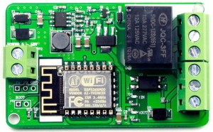
I purchased a few of these Yunshan Wifi Relays through ebay for approximately $7.50US. The device should be perfect for use in simple IOT projects which require controlling household AC power. The onboard JQC-3FF relay is rated to 250VAC or 30VDC at up to 12A. There are routered slots between the high voltage PCB traces for circuit isolation and arc-over protection. Transient voltage suppression is incorporated on both the board power supply and the photocoupler (see description below) input line.
The device requires a power supply between 7 and 30V DC. I unsuccessfully attempted to run it with an inexpensive 5V, 2A wall-wort, even though the onboard MP2303 buck converter is rated down to 4.8V. I did get it to operate successfully using a 9VDC wall-wort.
The device contains an integrated ESP8266-12E, but appears to only use the GPIO4 and GPIO5 pins. That was a disheartening discovery because it discards a significant amount of functionality inside the ESP8266 WIFI module. Hence the ESP8266 low power, wake from sleep provisions (where GPIO16 and RESET need to be linked together) would require some skillful soldering of the module’s exposed pins.
The good news is, programming the module is very easy, as I discuss later. I also found the overall build quality of my device to be above the typical level found on ebay-sourced Chinese electronics.
The ebay listing contained a link to a zip file, entitled U4648-datasheet, which contained example programs, schematics, and a Chinese manual. Through the Google translation service I managed to translate the manual, but there’s no reason to do that, as there isn’t much there. More information can be learned from a quick study of the schematic and the board itself.
Module Description
The Chinese manual presents the following limited module description:
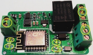
1 – The power input terminals.
2 – The relay output terminals.
3 – IO input terminal.
4 – Enter the status indicator, IO input high when lit, blue light.
5 – The relay output status indicator, the relay is turned on, the red light.
6 – TTL serial output.
7 – Boot mode selection jumper.
Board Connectors
Here are the connections on my board:
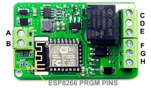
A: 7-30V+ DC power supply
B: Power supply ground
C: Normally closed (NC) relay contact
D: Common (COM) relay contact
E: Normally open (NO) relay contact
F: 5V+ out
G: ESP8266 GPIO5 Optocoupler Input
H: Ground (isolated optocoupler input)
AP MODE Webpage
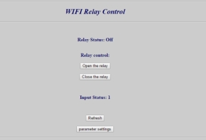
I was easily able to connect a 9V power supply to the A-B connector (see above picture and connector description) and control the device via WIFI. To do this, simply connect your computer or phone to the yunshan_wifi_xx_xx_xx network (where it appears the xx are hexadecimal numbers pulled from the ESP8266 MAC address). My device responded to the supplied password of yunshan123456789. Once a connection was established, I simply entered the IP address of 192.168.4.1 into my browser. Once there, I was greeted by a Chinese web page, the translation of which appears below. From this webpage, I was able to open and close the relay. The status of the GPIO5 optocoupler input is also displayed on this webpage.
Since I have big IOT home automation plans for these devices, my next task was to attempt a re-program of the onboard ESP8266 module. For a quick test, I uploaded the traditional Arduino IDE ESP8266 blink program, and was rewarded with a 1Hz blinking blue LED on the ESP8266 module.
Program Upload
On the lower left portion of the PCB is a section that grants access to the ESP8266 pins for programming (see the above photo). These same pins are also useful for TTL serial output purposes (debugging, etc.). Separate 2 and 3-pin headers will need to be soldered into these connector holes (labeled P5 and P6). The ESP8266 GPIO4 controls the relay through a 2N3904 transistor. Setting GPIO4 high, causes the relay to close the NO contact with Common and the NC contact to open. Additionally, taking connector “G” high causes GPIO5 to also go low isolated via a PC817 photocoupler. On my board the blue LED is connected to GPIO2, and can be illuminated by pulling the pin low.
To program the ESP8266 module, I connected the TX, RX and ground pins of connector P6 to a SparkFun USB FTDI programmer, and jumped the two pins of connector P5 together when I was ready to upload. Connector P5 grounds GPIO0 and GPIO15, sending the device into bootloader mode. If you have trouble programming the ESP8266 like I did on the first attempt, ensure you also ground your FTDI device through the P6 connector.
A very good introduction to the ESP8266 module can be found here. Excellent programming information for the individual ESP8266 modules is also widely available (two examples: ESP8266-01 and ESP8266-12e).
Board Schematic

Blynk Relay Control Application
/*************************************************************************
 * Title: Simple ESP-8266 blynk/yunshan wifi relay control
 * File: esp8266_yunshan_relay.ino
 * Author: James Eli
 * Date: 12/25/2016
 *
 * This program controls a Yunshan wifi relay module communicating through
 * the onboard esp-8266-12e module. The module is controlled from the
 * internet via the Blynk cloud app.
 *
 * Notes:
 *  (1) Requires the following arduino libraries:
 *      ESP8266
 *      Blynk
 *  (2) Compiled with arduino ide 1.6.12
 *  (3) Uses three Blynk app widgets:
 *       V0: button configured as a switch.
 *       V1: led.
 *       V2: led.
 *************************************************************************
 * Change Log:
 *   12/25/2016: Initial release. JME
 *   12/31/2016: Added input pin status. JME
 *   01/15/2017: Added volatile. JME
 *************************************************************************/
#include <ESP8266WiFi.h>
#include <BlynkSimpleEsp8266.h>

// Esp8266 pins.
#define ESP8266_GPIO2    2 // Blue LED.
#define ESP8266_GPIO4    4 // Relay control.
#define ESP8266_GPIO5    5 // Optocoupler input.
#define LED_PIN          ESP8266_GPIO2
// Blynk app authentication code.
char auth[] = "***";
// Wifi SSID.
const char ssid[] = "***";
// Wifi password.
const char password[] = "***";
// Flag for sync on re-connection.
bool isFirstConnect = true;
volatile int relayState = LOW;    // Blynk app pushbutton status.
volatile int inputState = LOW;    // Input pin state.

void setup() {
  pinMode( ESP8266_GPIO4, OUTPUT );       // Relay control pin.
  pinMode( ESP8266_GPIO5, INPUT_PULLUP ); // Input pin.
  pinMode( LED_PIN, OUTPUT );             // ESP8266 module blue LED.
  digitalWrite( LED_PIN, LOW );           // Turn on LED.
  Blynk.begin( auth, ssid, password );    // Initiate Blynk conection.
  digitalWrite( LED_PIN, HIGH );          // Turn off LED.
}

// This function runs every time Blynk connection is established.
BLYNK_CONNECTED() {
  if ( isFirstConnect ) {
    Blynk.syncAll();
    isFirstConnect = false;
  }
}

// Sync input LED.
BLYNK_READ( V2 ) {
  CheckInput();
}

// Blynk app relay command.
BLYNK_WRITE( V0 ) {
  if ( param.asInt() != relayState ) {
    relayState = !relayState;                  // Toggle state.
    digitalWrite( ESP8266_GPIO4, relayState ); // Relay control pin.
    Blynk.virtualWrite( V1, relayState*255 );  // Set Blynk app LED.
  }
}

// Debounce input pin.
int DebouncePin( void ) {
  // Read input pin.
  if ( digitalRead( ESP8266_GPIO5 ) == HIGH ) {
    // Debounce input.
    delay( 25 );
    if ( digitalRead( ESP8266_GPIO5 ) == HIGH )
      return HIGH;
  }
  return LOW;
}

// Set LED based upon state of input pin.
void CheckInput( void ) {
  if ( DebouncePin() != inputState ) {
    Blynk.virtualWrite( V2, inputState*255 );
    inputState = !inputState;
  }
}

// Main program loop.
void loop() {
  Blynk.run();
  CheckInput();
  //yield(); //Updated: 3/8/2017
}
TCP Client Demo
Here is a basic server which responds to TCP client HTTP GET commands (added 1/8/17):
#include <ESP8266WiFi.h>

// Esp8266 pinouts
#define ESP8266_GPIO2    2  // Blue LED.
#define ESP8266_GPIO4    4  // Relay control.
#define ESP8266_GPIO5    5  // Optocoupler input.
#define LED_PIN          ESP8266_GPIO2
// WiFi Definitions.
const char ssid[] = "***";
const char pswd[] = "***";
WiFiServer server( 80 );
volatile int relayState = 0;      // Relay state.

void setup() {
  initHardware();
  connectWiFi();
  server.begin();
}

void GetClient( WiFiClient client ) {
  // Read the first line of the request.
  String req = client.readStringUntil( '\r' );
  Serial.println( req );
  client.flush();

  String s = "HTTP/1.1 200 OK\r\nContent-Type: text/html\r\n\r\n<!DOCTYPE HTML>\r\n<html>\r\n";

  if ( req.indexOf( "OPTIONS" ) != -1 ) {
    s += "Allows: GET, OPTIONS";

  } else if ( req.indexOf( "GET" ) != -1 ) {
    if ( req.indexOf( "open" ) != -1 ) {
      // relay on!
      s += "relay on!";
      relayState = 1;
      digitalWrite( ESP8266_GPIO4, 1 ); // Relay control pin.

    } else if ( req.indexOf( "close" ) != -1 ) {
      // relay off!
      s += "relay off!";
      relayState = 0;
      digitalWrite( ESP8266_GPIO4, 0 ); // Relay control pin.

    } else if ( req.indexOf( "relay" ) != -1 ) {
      if ( relayState == 0 )
        // relay off!
        s += "relay off!";
      else
        // relay on!
        s += "relay on!";

    } else if ( req.indexOf( "io" ) != -1 ) {
      if ( digitalRead( ESP8266_GPIO5 ) == 0 )
        s += "input io is:0!";
      else
        s += "input io is:1!";

    } else if ( req.indexOf( "MAC" ) != -1 ) {
      uint8_t mac[WL_MAC_ADDR_LENGTH];
      WiFi.softAPmacAddress( mac );
      String macID = String( mac[WL_MAC_ADDR_LENGTH - 5], HEX) + String( mac[WL_MAC_ADDR_LENGTH - 4], HEX) +
                     String( mac[WL_MAC_ADDR_LENGTH - 3], HEX) + String( mac[WL_MAC_ADDR_LENGTH - 2], HEX) +
                     String( mac[WL_MAC_ADDR_LENGTH - 1], HEX) + String( mac[WL_MAC_ADDR_LENGTH], HEX);
      macID.toUpperCase();
      s += "MAC address: " + macID;

    } else
      s += "Invalid Request.<br> Try: open/close/relay/io/MAC";

  } else
    s = "HTTP/1.1 501 Not Implemented\r\nContent-Type: text/html\r\n\r\n<!DOCTYPE HTML>\r\n<html>\r\n";

  client.flush();
  s += "</html>\n";

  // Send the response to the client.
  client.print( s );
  delay( 1 );
  Serial.println( "Client response sent." );
}

void loop() {
  // Check if a client has connected.
  WiFiClient client = server.available();
  if ( client )
    GetClient( client );
}

void connectWiFi() {
  byte ledStatus = LOW;
  Serial.println();
  Serial.println( "Connecting to: " + String( ssid ) );
  // Set WiFi mode to station (as opposed to AP or AP_STA).
  WiFi.mode( WIFI_STA );

  // WiFI.begin([ssid], [passkey]) initiates a WiFI connection.
  // to the stated [ssid], using the [passkey] as a WPA, WPA2, or WEP passphrase.
  WiFi.begin( ssid, pswd );

  while ( WiFi.status() != WL_CONNECTED ) {
    // Blink the LED.
    digitalWrite( LED_PIN, ledStatus ); // Write LED high/low.
    ledStatus = ( ledStatus == HIGH ) ? LOW : HIGH;
    delay( 100 );
  }

  Serial.println( "WiFi connected" );
  Serial.println( "IP address: " );
  Serial.println( WiFi.localIP() );
}

void initHardware() {
  Serial.begin( 9600 );
  pinMode( ESP8266_GPIO4, OUTPUT );       // Relay control pin.
  pinMode( ESP8266_GPIO5, INPUT_PULLUP ); // Input pin.
  pinMode( LED_PIN, OUTPUT );             // ESP8266 module blue LED.
  digitalWrite( ESP8266_GPIO4, 0 );       // Set relay control pin low.
}

Hi Jim,
her article gives me hope. Try now for several days to find a solution to reprogram this circuit.
First of all, all circuits that I bought were broken by the hardware. All the coils had been soldered incorrectly and the fuses were also broken.
Repaired, I can now AT commands and adjust also. But I can not take a separate function from any of the circuits.
The circuit can not be reprogrammed.
My question to you:
You set the P5 (jumper) permanently during programming and RX TX = 1: 1 or RX cross TX.?
I have tried various 3.3 V FTDI’s some work not at all (seemingly felled cn).
Do you have a solution for me?
thank you
Peter
Sorry 😦 Google Translate
Peter,
So sorry you are having these problems. My devices worked correctly from the beginning. I hope I can be of some assistance.
(1) You must connect a separate and appropriate power supply independent of the FTDI programmer when programming. The FTDI programmer probably has insufficient power.
(2) P5 connector is meant to be jumped together only during programming. When programming is complete, remove the jumper and reboot.
(3) Connect your FTDI RX to P6 TX, and FTDI TX to P6 RX, and FTDI ground to the ground.
(4) Often when I attempt to program, the download will not occur. In this case, I simply remove the power from the device and reboot with the jumper in place, and then re-attempt the download. There is no need to disconnect the FTDI programmer. This usually works.
(5) I program via the Arduino IDE. Make sure you are selecting a generic ESP8266 module.
(6) Try programming at lower baud rates before trying a higher rate.
Jim
Hi Peter, same with me: fuses appear to be broken and coils rotated 90 degrees. weird…
The devices I received have a single 5-pin JQC-3FF relay. The pins are asymmetrical, so nearly impossible to solder wrong (but I guess its possible). Also my boards have just a single fuse on the 30VDC board power input line. Is it possible someone mistakenly applied AC power here?
Hello,
Sorry Jim a little addendum:
It’s been told wrong. It is the coil of the voltage regulator it is incorrectly soldered, it creates a short circuit and the fuse 500mA is destroyed.
Three unsung boards had the fuse already broken.
There was no alternating voltage, I’m an electronics engineer
My board is working, my problem was the reset. The board may only be reset shortly before the end of the slow compilation? (Timeout)
thank you
Peter
Hi Peter, can you show me a before/after picture?
nvm. turned out that only the f1 (apparently a diode) needed to be reversed. now everything a-ok.
Just a question…. this yunshan device is supposed to receive tcp commands. The question is… , what command do I use to turn the relay on and off with my tcp client? I did not find it.
I would suggest looking at the TCP Client Demo source code in the download link.
what is the command do I use to turn the relay on and off with my tcp client? I did not find it.
RTSL. “open relay!” and “close relay!”
Great ! Those are working. Thank You Jim.
Can you also tell us please the commands for
1. Input status
2. Relay status only (without activating or deactivating the relay)
3. Other commands if any.
Try “get relay state!”, “get io state!”, and “get MAC!”.
Thanks Jim. All of the commands you suggested did work.
At WhatsApp distance si posible to comando this relay ?
At the distance of the internet.
hi guys, I purchased one of these from china.
I can only get start if i bypass the fuse F1, by connecting the + to the right side of the diode ( M7 ) should this not be a fuse instead as?
It turned out that the M7 diode was soldered in in wrong direction. I turned it around 🙂
Yes. I had this M7 diode experience as well with unit purchased from Amazon. Furthermore, this unit came blank (not programmed) and I returned it. Over 20 different vendors are selling same device on eBay. Mostly from China and 1-2 local in the U.S. Bought another one from US Vendor on eBay. I managed to activate the web interface for this one, but FTP doesn’t work. Port 8000 is open and listening but commands like “relay on!” or “open relay!” do not work.
I may have the same issue…how can you tell which is the correct direction of the diode?
Jim,
Like you I had big plans for this device and purchased 5 from Amazon along with 5 12V DC power supplies..
Unlike you I’m not set to do the programming of it.
I trusted some Amazon reviews that the device is not perfect but workable and can be accessed by HTML and FTP similar to what you describe.
To my great disappointment the device creates only own unsecured WiFi called AI-THINKER. It has IP address 192.168.4.1 and does respond to pings. That’s all. I scanned for open ports/services – none. I specifically looked for TCP service on port 8000 (link from Amazon review mentioned this port specifically for FTP) – none. No web service either. It seems that this is blank AI-THINKER device not programmed with Yunshan features as described at Amazon.
Based on your experience, am I missing something here or should I return everything to Amazon.
Did you get yours from US vendor on eBay or from China?
Ivan,
I didn’t spend much time playing with the installed software, other than to test the AP mode webserver. I briefly looked at the demo software I mention in the download zip file (see link in blog). Response for a TCP client appears to be implemented in an entirely different program than the version that was installed on my devices. My guess is that what you are looking for isn’t there. I suggest you install what you need, as programming is really easy (especially when using the Arduino IDE). Good luck.
Jim
I got the same AI_THINKER. I can ping as well, but port scanner shows no port open
Jim,
Thanks for the response. Appears that Amazon is selling visually the same device with different programming (blank actually) while the description is for Yunshan programmed device.
Anyhow, I returned it to Amazon and bought true Yunshan device from eBay.
It matches your description above perfectly all the way down to your “Program Upload” paragraph.
Since I have no intention of uploading programs (not qualified for that) I was wondering if you can help me setting up the device. I can connect to it trough its own wifi network to address 192.168.4.1. I can see the web page, however none of the buttons work. Browser tells me “No Internet connection”. Of course no Internet since I’m connected to the device alone. I also managed connecting to TCP port 8,000 however it will not respond to any of the commands “relay on!” or off. So basically I’m stuck again.
Thanks,
Ivan
P.S. Managed to connect the device to my WiFi network. I don’t know why but it needed Internet connection for that. So I used a desktop computer with wired connection to the Internet and WiFi connection to Yunshan WiFi.
Now I can control the relay over the web interface. However the TCP commands “relay on!” and “relay off!” do not work.
My postings seem somewhat off topic I just couldn’t find a better place to share my experience and help others who may struggle with the same Chinese problems.
My objective is to integrate the relay in my IoT system by standard means (HTTP or FTP control) There are many other solutions on the market however most of them are proprietary with secret hidden protocols and hard to integrate.
Hi Ivan, I wasn’t able to connect it to my WiFi network. I’ve put the network ID and password in Yunshan WiFi settings over 192.168.4.1 web interface, using my laptop. If I try to connect to web interface over my phone, the commands doesn’t work, because no internet is available. Is there a catch?
Hi Jim,
It’s me again. As the French proverb goes “Appetite comes with the eating”. I have the Yunshan relay completely under control now incl. commands and responses. Thank you again for the help on the commands.
I’m now interested in extending the functionality as explained below. Is it possible for you to write the code that is needed and guide me step by step of how to upload it. Contact me privately how to get paid for the time and effort.
In many instances one needs to introduce “timeout” feature when controlling significant power trough home automation – examples – pool pumps, sauna, steam room, electric room heaters etc. It can be implemented trough software but it defeats the purpose since the timeout is there to kick-in when the controlling software/system fails. That’s why it is preferably that the timeout is implemented outside of the control system and is build-in in the firmware/hardware at lower level.
Long story short I need the relay to execute a command like this
relayon, t
where t= timeout in seconds,
if t=0 then no timeout
the relay will turn on and than turn off automatically after t seconds
In addition to timeouts, this function will come handy in creating short pulses that are necessary to operate some devices such as garage doors for example.
of course such function can be achieved by adding external timer relays, but it wouldn’t be an elegant solution.
Thanks for the code! got me running real fast 🙂
Only using the Relay for output atm, how would I use the input?
do I need to ground it or apply 5V or more?
Would like to connect it to a Speaker for a wireless doorbell and get notified when it rings 🙂
Cheers!
Ivan, I have a suggestion for you if you haven’t already worked out another solution. There is firmware for the esp8266 called Esp Easy that has considerable flexibility to perform different tasks in different esp8266 based hardware without requiring re-compiling or reloading it into the device. It can be downloaded in binary form so you don’t need to setup the Arduino environment to compile or load it into a device. There is a simple windows tool to upload the firmware to the esp8266. I have successfully loaded it into this relay board as well as other esp8266 based devices and been able to do what I needed to do with my home automation system.
Even though I have a working Arduino IDE that I’ve used to do things with the esp8266, my go to solution is Esp Easy for these simple esp8266 IOT devices.
For the USB/TTL hardware interface, I prefer ch340g based converters even though I own FTDI and CP2102 ones as well. The ch340g boards are cheap and I’ve never had any issues with them (they also work fine with the Arduino IDE). Whatever interface you use, be sure it can work with 3.3v logic levels, most boards have a switch or jumper to go between 3.3v and 5v. If you have an Arduino UNO, that should also work to do the programming but it’s not as straight forward as a stand alone USB/TTL converter and I haven’t tested it with the uploader.
If this is a path you want to explore, I’ll be happy to give you some pointers.
Thanks for the heads up about ESP Easy. It was fairly easy to upload firmware (after getting a flash program that would work. flashESP8266.exe did not work for me on Windows 10, returning a file not found error).
After simple config to connect to my network, I can now use simple http get cmd to turn relay on and off.
Zeric, Thanks a lot for the proposal. I did hire a freelancer to do the programming for me but I’m also curious and eager to try Esp Easy for other projects possibly. I will appreciate a guidance of how to do it. I have this device for uploads – Qunqi 3.3V 5.5V FT232RL FTDI Usb to TTL Serial Adapter.
Ivan, Your Qunqi adapter should be fine as long the device driver is working okay with your PC. Most people on Amazon didn’t seem to have any issue with it. Just be sure you have the jumper set to 3.3v. There is quite a bit of information on Esp Easy here: http://www.letscontrolit.com/wiki/index.php/ESPEasy
Esp Easy was originally designed for sensors, but it works well controlling simple on/off things like relays too. Enabling “rules” in the Tools > Advanced menu enables it to perform some simple definable autonomous function (ex. when this pin changes state, turn on this other pin for XX seconds). I use it with an MQTT broker, but other types of access are also possible such as HTTP. I’ve been impressed with the flexibility without having to re-compile/upload.
It’s worth taking a look at when you have a chance.
Thanks will do.
Ivan,
I’m looking for the same functionality as you. I first want it to be able to take an http command to momentary close the relay for my garage door. Did your freelancer implement this, and if so, are you willing to share? I’d contribute to the cost
Jason
Hi jim, in your opinion is it possibile use the Optocoupler Input for a 220v Main sense?
Larks,
My version of the device came with a PC817 Opto-Coupler. I think it’s only spec’d to handle around 30 volts. Since 5V out is shared on its connector, I’m guessing it was designed to be used at that level.
If we use the bridge R1 and D1 as on the following assembly. It should work?
http://www.electroschematics.com/6994/220v-power-line-interface/
This will not burn anything but is not a good solution because of the sine wave there will be periods of low current and false readings of 1 when power is present. First determine what current I holds solid steady 0. Say it is 1 ma. Than build a simple rectifier one diode (better 4 diodes bridge widely available) and one capacitor will do the job for such low current. Than measure the voltage on your rectifier say 200 V. Connect the IO input trough a resistor R. R=U/I. For the example R = 200/0.001 = 200Ko. Check the power on the resistor (approximately ignoring the voltage drop on the optocoupler) P=U*I. For the example P=200*0.001= 0.2 W. This is acceptable power level, however if the real values show power over 1.0 W it may get too hot.
But the input has just an R of 4,7k on input in the schema… In this case is sufficient a Diode before? Which task has the parallel diode(D5)?
Thanks for info, i’m newbie 🙂
The parallel diode prevents negative portion of the sine wave from hitting the opto-coupler. This schema will work if implemented completely as shown. It will not work if you implement only the portion that feeds the opto-coupler and leave the rest to Yunshan board. Follow my instructions above for a much simpler solution for the Yunshan board.
So what all applications does this opto isolator have? is it for just input or output too?
Cool little project Jim, thanks for leaving it for people to try.
I’ve successfully burnt your code to my Yunshan board and made a small Blynk app to control it. The only thing is that it loses the wifi connection after a period of time and doesn’t seem to attempt to re-connect so I just get a message from Blynk telling me that “device went offline at xxxx” and I have to reboot the board to get everything working again. Any ideas?
Nick,
My device has dropped offline a few times too. I haven’t had the time to fully investigate this, and I’m open to suggestions. Here are a few of my initial thoughts: (1) Is the power supply adequate? (2) Is it an issue with Blynk, ESP8266 or the WIFI router side? (3) Would the the ESP8266 boot ROM log shed any light?
However, since some of my other devices don’t have this problem, I’m thinking it might be a HW/PS issue.
Jim
Hi Jim,
The power supply is fine (it’s a regulated lab power supply, easily big enough). The router to ESP Wifi connection is strong and so I doubt that’s a problem. Yesterday it was online for some hours and then went off shortly after midnight. This morning I tried to reboot the unit a few times without success (just blue LED showing no connection). I tried re-flashing the code to the ESP and that worked.
The only thing I can think from my end is that our connection to the internet can drop out for a minute or two (this often happens around the time the unit went offline, just after midnight) so hence my earlier question. I’m afraid code-wise I’m a newbie at this stuff so can’t really help de-bug at that level. I’ve tried a couple of Sonoff devices in the same place and they work fine.
Wonder if anyone else has had issues like this?
Thanks!
What voltage are you driving the device at?
Just looked at the code, and here’s a thought, try eliminating the “yield” command inside the main Loop.
It’s 12V.
Will try the yield thing and let you know. Thanks
Well, code is still working after removing the yield. Will leave the module on and unattended and let you know. In fact I might try turning the wifi network off for a minute and see if the module tries to re-connect by itself.
Just tried turning off the wifi and the module re-connects and starts working again when the wifi comes back up.
*fingers crossed*
Hi Jim,
Well, that seems to have sorted it. The module was on for over 24hrs without a problem. Whilst doing other stuff nearby I knocked the power supply leads a couple of times and the power was lost briefly; both times the module powered back up and connected to wifi and the Blynk server within 3-4 seconds. I’ll keep you posted if anything changes. Thanks!
Hi,
Did you really manage to make the relay switch? I’ve bought three of those network boards but no luck switching the relay. After flipping a diode where a fuse needs to be, I can make everything work and when I switch the relay the output LED will go on but the relay does not switch. After removing the MP2303 Buck converter on one of them and connecting 5V directly to the LM1117-3.3V it does switch the relay. So I checked the output of the MP2303 on the other two boards and it seems to be configured to give 3V3. So it provides 3V3 to the LM1117-3V3 which gives 2V5 on his output, enough to power the ESP8266 but the 3V3 is to little to switch the relay…
I checked the values on the boards and they are all the same as on your schematic. It’s just weird I’m having this issue on three boards?
After reading Peter his comment, I can confirm that the coil of the voltage regulator was placed incorrect. Although there are no fuses but diodes on the boards, replacing the coil solved the issues.
Conclusion: bad build quality although different suppliers..
BTW, I think when you replace the diode with a real fuse you will not have a voltage drop of 0.7V over the diode. Giving you the possibility to use a 5V power supply (5-0.7 = 4.3V which is below the 4.8V minimum)
now I got hold of another one, this has Resistor R8, 52kOhm instead of 4.7k, so the input doesnt work, what a quality…. how difficult would it be to test 2 out of the 2 functions.
It seems that there’s a large variation in the build quality of these boards. I bought mine (just one) from Ebay and it worked first time. The link is here…
http://www.ebay.co.uk/itm/142240467734
Also, for the optocoupler input you need to provide a second ground reference. This input is totally isolated and needs it’s own ground and voltage supply to trigger the opto.
thank you very useful information – mine had has well diode soldered wrong around.
Hi, I intended to hook up the device to my home network and access it with TeamViewer. There is a problem with hooking up. I’ve managed to access the web interface via 192.168.4.1 and I’ve entered user name and password of my home wireless network. However, I’m only able to change the state of relay if I’m directly connected to its wireless network (yunshan_wifi_xx_xx_xx) via laptop. This means that I cannot change its state from my phone, since the phone disconnects from home wireless network to connect with relay wireless network. It seems that relay is not connected to home wireless network at all.
Did anyone have similar problem?
If you can program the board using an RS232 converter and PC then upload the code at the top of this page. You then use a program on your phone called Blynk and use that to control the module. The software that comes already installed when you buy the board is not very good and just a demo really, in my opinion.
Thanks, Nick. That’s too complicated for me, though. I’m just a guy trying to find a way to make it work. 🙂 Have you tried to change the state of the relay over the web with its pre-installed software, as described in Chinese manual?
Since my board, does not seem to produce an SSID, when it’s powered up, am I correct in thinking it’s not properly programmed?
Make sure you provide enough voltage to the board, the esp8266 needs an appropriate amount of juice before it works properly. Otherwise I would assume so.
Thanks, I have been merely using a 9 volt battery, will try a 12 volt source instead.
Hi Jim,
did you managed to read the input correctly? For me, reading GPIO5 is always “1”, even if I connect “F” to “G”.
I flashed nodeMCU to my board, anything else is running fine, also switching the relay. Putting GPIO5 to OUTPUT-State is also possible, the little blue LED can be put on and off.
Anybody else some experience with reading input?
The optocoupler has a (properly) isolated ground, so the 5V out is reference a different ground. Therefore, simply connecting F to G will do nothing.
Thank you Jim,
that solved my problem. Connecting the external ground (“B”) to connector “H” did the job.
HI thanks for sharing your knowledge with thit esp8266 board
I use this with http://souliss.net/
The opto isolated inot don t work proply.
I think is a hardware issue
I read r8 is only 1,5 kohm not 4.7
When I power the board the input is 0 when i change value the input became 1
the led power up, but when I try to return to lower state the input remains 1 and the led Is always on
Ok I shortcut the input led and now work! I think the led is mounted reversed
HI,
Does anyone know this module?
can you help me?
I can not make it work with arduino IDE … help
http://www.chinalctech.com/index.php?_m=mod_product&_a=view&p_id=1204
http://www.chinalctech.com/index.php?_m=mod_product&_a=view&p_id=1205
Sir, it would be of an immense help to me if u can explain how to work with this module. i tried to open the homepage, but it’s all Chinese. I am clueless. any help would be appreciated.
That’s he purpose of this post. Please read it carefully.
is there a way to send AT commands over wifi from my laptop and is there a way to override the homepage of yunshan wifi relay
hey! this tutorial was of immense help! it’s awesome of you to share this knowledge with all of us beginners. but i have a question. Can i use this device to send live data via a udp channel or udp port so that i can monitor it live from a web server? Because I intend to use it to monitor the rpm of machines(bys giving input to optocoupler isolator pin G).
Hi Jim
Thanks a lot, for this post, I managed to get the Yunshan IoT module up and running interfacing with Blink after Flushing it with your code… However now I am attempting to add additional Hardware, second Relay connected to GPIO14 and a second Opto coupler connected to GPIO12, I designated V10 to second Relay and V11 To second Opto coupler.
I duplicated the code where required, but seems to be stuck by my limited programing skills.
Please may I ask for some assistance.
Many Thanks
Lodie
How are you wiring to GPIO12 and 14, these pins are not brought out to a connector? I would venture to guess your issue is hardware related and in the wiring (shared grounds?).
can you explain how to use the optical input
See the TCP Client Demo program (GPIO5).
Hi Jim
I actually constructed a totally new project on pc board , adding an ESP8266 module, The Relay and Opto coupler circuits are duplicated only IO Pin designation differs. With your version of the Sketch I am able to successfully operate GPIO4 (V0) and GPIO5 (V2). I would like to add GPIO14 (V3) As Output for the second Relay, and GPIO12 (V4) as Input from Opto Coupler.
Thank you so much for the board pinout and schematic diagrams. I bought a couple of these boards off AliExpress on impulse and they came with no documentation whatsoever (mine were marked “HW-622” for anyone else searching). Using your pinout and PlatformIO I got the relay up and clicking away on GPIO4!
Hi
It is possible to program this relay board using Arduino UNO microcontroller and its RX TX pins?
If it is possible to program the esp-8266 via an UNO, then yes. I have never tried this.
Hi Guys,
Just want to add my two pence worth.
I bought a couple of these from ebay and they both have the diode and fuse swapped over. This means the fuse is in parallel with power supply so would have been blown at testing in the factory.
The diode is now in series with power supply and on these boards is in the forward bias direction. The diode on my board is marked ‘MZ’ which means it has a reverse breakdown of 51 volts, but more importantly the spec sheet says it has a forward voltage drop of 3.5 – 5 volts. This means if you are trying to power it from 5 volts, it aint gonna work. Those of you using 12 volts will not notice a problem as the regulator will be getting around 7 volts anyway. 9 volt input could be marginal, especially driving the relay.
The simple way out is to short out the diode and make sure you get the power the right way around, or just parallel another normal rectifier diode across the existing one.
Cheers
Kev.
This was a great article. I learned a lot. I modified your TCP Client Demo slightly and it works great. There are a couple of minor bugs in your code. I noticed that my DHCP server saw a different MAC than what your sample returned. The first thing I noticed is that the index to read the value should be 0 to 5 not 1 to 6. There are always 6 bytes so I don’t know why you used the length function. Secondly you need to use WiFi.macAddress( mac ); instead of WiFi.softAPmacAddress( mac ); Here is my code:
WiFi.macAddress( mac );
String macID = String( mac[WL_MAC_ADDR_LENGTH – 6], HEX) + String( mac[WL_MAC_ADDR_LENGTH – 5], HEX) +
String( mac[WL_MAC_ADDR_LENGTH – 4], HEX) + String( mac[WL_MAC_ADDR_LENGTH – 3], HEX) +
String( mac[WL_MAC_ADDR_LENGTH – 2], HEX) + String( mac[WL_MAC_ADDR_LENGTH – 1], HEX);
http:///open turns the relay on.
http:///close turns it off.
http:///MAC reports the MAC address.
Thanks again,
Allen
Jim,
Thanks for the tutorial. Lots of good info. I have it now running. Curious, do you remember the settings you used on Arduino. I had the same problem with a 5V wall wort. Mine started whining after a couple minutes. Changed to 9V. I have it working on the Alexa. Works pretty well.
Again, thanks
Dan Powell
Really useful page, thanks, as my module arrived without any documentation at all, not even polarity indication for power in.
Can you explain what the “Optocoupler input” is? As far as I can tell from the example sketches, it’s a simple digital input pin. I don’t understand in what sense it is an “Optocoupler” input.
More specific question: can I use it as input for a DS18B20 one-wire temperature sensor? (I’m looking at using the module for thermostatic heater control.)
Opto-coupler means that your sensor or whatever device you connect to this input will not connect electrically to the relay board. For example you can connect high voltage device there that otherwise will damage the board but with the opto-coupler it will not. Of course some precautionary measures have to be taken not to damage the opto-coupler itself. As far as 1wire sensors go, yes it is possible however proper additional programming needs to be done at ESP8266. It won’t work as is.
Jeff,
>Can you explain what the “Optocoupler input” is?
An optocoupler is generally used to isolate separate circuits from each other, typically when different or dangerous voltage level exits between them. In the case of this device, the connectors on the board labelled F, G and H are separated from everything else. F is 5v output, G is the optocoupler input and H is an isolated ground. This is probably designed for incorporating a low voltage, human-operated switch, which would be isolated from high voltage main power.
>More specific question: can I use it as input for a DS18B20 one-wire temperature sensor?
I doubt it, the optocoupler is not bi-directional. I’ve never tried it.
Jim
Thanks Ivan, Jim. I understand the idea of optocoupler as an isolator; I just hadn’t thought about the input side. That makes a lot of sense, and I agree (now that you’ve explained!) that it’s not going to be bidirectional.
I can do one-wire programming, but the problem here is that none of the other IO pins are brought out to connectors. Any suggestions of a way to get access to one or more? My best (only!) idea so far is to solder a wire directly onto the ESP’s pins; I do understand the risk to the chip of trying that!
I wonder if you could solder to larger pin pad at the optocoupler? You could even remove the whole oc chip [https://www.youtube.com/watch?v=N_dvf45hN6Y]
With a swift swipe of a very hot soldering iron, I managed to solder a lead directly onto the GPIO13 pad without either shorting anything out or overheating the chip. Thanks Jim for including the pinout on the board schematic. (I confirmed it with a voltmeter and a sketch that toggled it once a second.)
I now have a thermostatically controlled heater! Next step is to add a web interface for controlling it. (Back in the realm of software, where I’m much more comfortable!)
FYI, I’m powering it with a 6V/1A mains adapter.
Fantastic!
Hey Jim, this article was immense help and I was able to work with this relay board. However there are some basic questions which am not getting and hoping you can help clear out the confusion.
– What are pins F,G & H used for? Although you have described the pins, I guess am lost there. Without connecting anything to these 3 pins, everything works normal for me.
– Pin F, you say it gives 5V out (correct me if I’m wrong here), can I use this current to power on the board i.e. on pin A?
Pins F, G and H would be useful for connecting some sort of switch/sensor that could control the relay. The 5V output would be used to power the sensor, it is not suitable for powering the board.
so, you are saying is that I can use these pins as a manual override as in I can control the light with manual toggle switch plus the ESP as well?
Also, do you have any practical use cases for these pins that you can think of out on top of your head?
Finally, all over the internet there is only this article related to this particular board, do you have to know of anything else which gives me basically the circuit diagram for this board.
1. Yes.
2. You just gave one yourself.
Circuit diagram is posted on my blog
Simply wire a momentary switch between the 5V and optocoupler input lines. Both of my example programs demonstrate how to detect switch activation with simple debounce functionality. Good luck.
hi,
i connected a momentary switch between:
G: ESP8266 GPIO5 Optocoupler Input
H: Ground (isolated optocoupler input)
But i dont get any response when running your code example on my board. did i miss something?
thanks for your help
You missed something. That’s not how an optocoupler works: https://en.wikipedia.org/wiki/Opto-isolator
i spend some time to understand how the optocoupler work and tried to find some examples how to connect everything…but now i am totally confused, because i don’t find any example with three terminals.
it would be very kind, if you could give me a helping hand and show me how to connect a momentary button to switch the relay by pressing a button.
thanks for your support!
Thanks. This was the only place I could find a schematic for this board.
I bought mine from eBay in early ’18. Out of the box, I couldn’t get any response to the “AT commands”. I re-flashed it with esp-easy.and it appears to be working fine. It behaves as all my other 8266 do. Hope this is of interest.
Can this kit running uPython ?
Pingback: Opensprinklette Single! | organic~monkey~motion
Thanks for the post – As others have noted, information on this board seems to be scarce. Was about to throw mine in the bin before I found this page…
May still do so 😦 Am getting no response at all from the board via wifi, serial, or led. Have connected 10vdc supply, and traced power all the way through to U1 pin 2 – but am only getting 1.2vdc on L1, R4, C5 and C6. My interpretation is that the voltage regulator is faulty. My old eyes would have trouble with the replacement of U1, but my solder kit is nowhere near up to the job for surface mount components anyway.
Any “last gasp” suggestions or do I just write it off as a failed experiment?
Thanks in anticipation
Hello guys,
I bought 2 new board but I got problem during download coding. I connected ESP module to arduino mega 2560 as wiring below:
Arduino mega 2560 ESP module
TX ———- TX (J6)
RX ———- RX (J6)
GND ———- GND (J6)
9 VDC ———- (+) (J2)
GND ———- (-) (J2)
PC connected to arduino mega 2560 via comport COM4 then I try to donwload program ( During download, The blue led on ESP8266 is flasing ) but download failed and the message error show:
warning: espcomm_sync failed
error: espcomm_open failed
error: espcomm_upload_mem failed
error: espcomm_upload_mem failed
Can you please tell me where my mistake?
Note:
– Didn’t remove J5 using for connected GPIO0 – GND during reboot and download
– Board selected on arduino is “Generic ESP8266 module”
Thank you for your help!
Pretty sure you have your RX and TX hooked up wrong it should be RX–>TX and TX–>RX
Even when changed as your recommendation the problem still have not been solved.
Additional when I connect RX–>TX and TX–>RX, the blue LED on ESP8266 chip didn’t flashing?
Btw, When I made hooked up as above then open serial monitor window and boot the ESP module, some information reply look like connected has been established but It not respond with the AT command and I still cannot uploading my program
The message is “ets Jan 8 2013, rst cause :1, boot mode: (1,5)”.
Try unplugging (power module terminal (1)) the ESP8266 while the USB – TTL is still connected to your PC. Plug back in and try to upload the program. It worked for me. I also noticed I need to unplug / plug to upload again.
Is it F: +5V output or input? Looking at schematic in U2 it states VIN for 5 V+. If I connect the Grounds: H to B, I am able to power the board from F with +5V as input.
But I found problems wiht the INPUT G … my boards RESET when I connect +5V to G. I also tried powering the boards with 12V on A, B and same problem.
Are my boards faulty? they don´t have the YunShan QR printed on the back !!!
Does someone face same problems configuring the INPUT in GPIO5?
// — Connected ouput pin.
#define RELAY_PIN 4 //ESP8266_GPIO4
// — Connected imput pin.
#define BUSY_PIN 5 //ESP8266_GPIO5
boolean busy;
// — Board Blue LED.
#define LED_PIN 2 //ESP8266_GPIO2
BR/A.S.
You can quote me, “F: 5V+ out”.
Thanks Jim, but still same problem. If I shortcut the grounds B with H, and I try to give a pulse of 5V to G from F, the board reboots.
I also tried to use an external 5 volts charger, directly connected to G & H but nothing happens and when I measure the voltage beteween G and H it only messures 1 volt … any advice?
I have no idea what you are trying to accomplish. Are you trying to use the optocoupler as an additional input signal? The board is powered via A and B and needs about 7-9 volts to operate. The esp8266 can then control the relay which connects through C, D and E. F, G and H can be ignored unless you want to use them for an additional input signal.
Exactly, I want to use F, G and H for an additional input signal which will be disable the logic to operate the relay.
Dear Jim, I found the problem, the Diode was soldered in the wrong direction so the hardware was faulty. Thanks for your time !!!
Ciao Antonio Solano.
So did you managed to use F, G (and maybe H) as input to toggle the relay? Did you reversed the D5 diode? If yes, can you share some info on how it works?
Actually I’m running EspEasy and I’m able to control the relay on GPIO4, the esp led on GPIO2 and only the input led on GPIO5.
Thank you!
Michele
Diode D5 soldered the wrong way around, check! Had the same issue. luckily I connected an open collector ciurcuit to the optocoupler input which made debugging a no brainer.
Thx very much @Jim for providing the schematic
Can someone post a picture of the “correct” or “incorrect” soldering of this board? Specifically the diode in question? I understand they have chosen t use the diode as a fuse – Is there a specific fuse that could be recommended to replace this (*and thus allow 5v supply to work*)?? Thanks in advance.
D5 is the ESD protection diode in the lower right corner in the above pictures. It is used to protect the optocoupler input. There is an easy way to check if D5 is problematic. Connect a 10k Ohm resistor between points F and G. If you measure 5V on input G you are good. If you measure less than 1V then D5 needs to be reversed.
D3 and D5 should be bidirectional diodes; so – given, that those devices are onboard, there is no need and no sense to reverse them. However it seems that our Chines friends might sometimes run out of these bidirectional diodes and replace them by unidirectionals – and then there is a 50:50 chance that they are soldered right or wrong. @Jim’s schematic shows the bidirectionals. Those diodes are meant for ESD/TVS (Transient Voltage Suppressor) overvoltage protection.
So far, I was lucky to flash my board with Tasmota; I used a USB FTDI programmer at 3.3V; connected TX-RX, RX-TX, GND-GND. To get the device powered by my USB-programmer I temporarily soldered a male header pin onto the AMS1117 (same as LM1117, if your board comes with that voltage regulator). The header was soldered onto the “big” tab of the AMS1117; the tab is Vout = 3.3V, same as the middle pin; but soldering on the tab is easier 😉
I used the flashing method of “Vicious Computers”, which is by far the fastest and simplest method so far and is explained in an excellent video here: https://www.youtube.com/watch?v=UDnNI5wkNNY.
Now I have full control of the relay including Tasmota’s features with timers, MQTT etc.
Hope that helps others a bit to use their WiFi relays.
Is it possible to upload pictures here? I get it to work in several ways. And this article is great. Thanks
Thanks for the tutorial. I purchased some of these from Banggood and they had none of the hardware issues described by some of the less fortunate. I used Arduino 1.8.9, added the https://arduino.esp8266.com/stable/package_esp8266com_index.json as my ‘Additional Boards Manager URL’ in preferences (as described in https://github.com/esp8266/Arduino), selected ‘Generic ESP8266’ board, connected my USB to serial board between this hardware and my PC and away we go!
On my board :
C is NO
E is NC
He Jim (and al other people reading),
Question, I power the board with 24V
Connected a machine to G and H that gives 24V when working and 0V if finished.
If finished I close a air valve with the relay.
Works perfect.
But now I need to ring a buzzer when the machine is finished.
I run easy ESP on the board so could program it with the rules.
and solder the buzzer straigt to one of the spare GPO pins on the board.
BUT the buzzer needs 24 volt.
can I connect the buzzer + straingt to my power supply and (for example) GPIO13 and set GPIO13 to LOW to buzz the buzzer?
Or does it not work this way???
its a small buzzer, runs from 3 till 24V but for the sound level I need 24V
https://nl.aliexpress.com/item/32955065577.html?spm=a2g0s.9042311.0.0.27424c4dutm5VJ
>
can I connect the buzzer + straingt to my power supply and (for example) GPIO13 and set GPIO13 to LOW to buzz the buzzer?
Or does it not work this way???
<
No! You would destroy the Yunshan ESP8266 board. You need to have the esp8266 activate the buzzer through a relay, transistor or mosfet.
For example: https://electronics.stackexchange.com/questions/38098/simple-design-to-switch-24v-from-pic
Ah thanks for not destroying my board 😀
I Try to fix it with a transistor but with no result, (not that good at elektronics)
Maybe you could give some advice.
I have these transistors:
pn2222a
2n3904
and a p16nf06 mosfet
I have try several configurations but non of them worked out the way it should.
I asume I can use them without a resistor of diode?
oke found it, needed to ground both power circuits together, did not know that 😀
https://startingelectronics.org/beginners/circuits/arduino-buzzer/
does anyone know if there is a similar board with two photocoupler inputs?
Late to the party here. I just bought two of these things and the information in this thread was what led me to buy them as the listing had no info. On my boards F1 fuse was a diode marked M7 which seems to be a rectifier diode, 0.6V drop. With it in place my board wouldn’t work with 5v input, even without it 4.8V was low enough to stop the esp8266 from booting. Next to F1 there is a component D3 marked “CM” which is meant to be some sort of input protection diode smbj33ca from schematic above I dont know if it is the misplaced fuse or not, there’s another one between the input to the opto isolator and ground, evidently to protect that too but on schematic that is smbj6.5ca, could speculate that the 1st one is meant to break down at 33v and the second at 6.5V. I am going to assume they are both blown fuses, ie that i dont have any input protection at those places. The mp2303 buck converter doesn’t seem to be as efficient as I was hoping for, I guess that when wifi is not being used the current draw is lower than the rating. I may well enable deep sleep so it doesn’t drain my battery too much
Hi Jim,
I just discovered this post and comment trail. Thanks for provoking it. I learned more in the last hour than in the previous 12 since I ordered some of these boards. I ordered the WeMos branded ones from Banggood (ID: 1089200). I’ll know to check for the misplaced diode and fuse when they come in. Anyway, I have a question about the input. My application for this device is to convert an input pulse from a relay closure into two output pulses with a controllable delay between them. I plan to use the ESP8266 in AP mode to allow me to adjust the time delay via some TBD technique on a web page. My input signal is from a set of relay contacts. From looking at the schematic it appears that I should connect to +5 and Input on Header 3. This would provide about 1 ma through the 4.7K resistor into the optocoupler. Will that be enough to operate it?
Thanks for any feedback,
Leon
So I received a version of this board, where they put a 10k resistor at R6, instead of 4.7k.
The relay doesn’t budge.
Does the LED (D2/LED0) light up?
I was one of the early adopters of this little board and now a have deployed more than a dozen. I’m using software from zumungo dot com to unleash tons of features. Here is a list of it
Free library By hardware vendor Zumungo
On/off by HTTP.
On/off by smart phone app.
On and off after selected timeout.
Overlay mode. Input status overrides the normal operation in any mode.
IO mode relay follows the status of an Input
Mono mode normal triggered by a transition at the input.
Mono mode recurring re-trigerred by every transition at the input.
Mono mode kill second trigger negates the action of the first trigger.
Select polarity of the input signal
Schedules – weekly, daily and hourly up to 3 schedules with up to 6 on/off events per schedule. Absolute time or relative time to sunset and sunrise.
Geo location
Report status of all relays and inputs
MQTT protocol for control and reports
TCP protocol for control and reports
HTTP control and reports (not just on/off but all other functions)
UDP protocol for reports
CallALL feature to locate multiple boards on the same network or recover forgotten IP address.
Own web page for settings
OTA (over the air) updates
Trigger by “1wire” temperature sensors
Up to 20 1wire temperature sensors
Custom temperature trigger levels and hysteresis
JSON API for control and reports of the temperature features
Completely customizable for integration with third party products
Can work stand alone once programmed.
Leon, yes the LED does blink, the relay does not budge. (LED & Relay are on the same circuit…as according to the diagram from blog post).
I desoldered the 10K smd resistor and replaced it with a 4.7k through-hole resistor, now the board functions as expected but the frankenstein thing looks ghetto as hell. I think I like it more now :p
I haven’t had the time to test the input siide of the board yet. (For me the output/relay is the primary function).
I just received my boards from Banggood (ID: 1464129), I’m not off to a good start. What should happen when I first connect power? Is there a power LED? Should it create a WIFI access point? Should it spit out some boot up info on the serial line. Mine doesn’t seem to do anything. And I get no response when I connect to the serial port. I’m sure the FTDI adapter is working since a loopback test shorting the RX/TX terminals worked fine. Any suggestions?
AP MODE Webpage
“I was easily able to connect a 9V power supply to the A-B connector (see above picture and connector description) and control the device via WIFI. To do this, simply connect your computer or phone to the yunshan_wifi_xx_xx_xx network (where it appears the xx are hexadecimal numbers pulled from the ESP8266 MAC address). My device responded to the supplied password of yunshan123456789. Once a connection was established, I simply entered the IP address of 192.168.4.1 into my browser. Once there, I was greeted by a Chinese web page…”
Some of them have firmware, some don’t.
Firmware or no, on the serial line you will see the boot information when you power it on.
Take note that these do not boot on 5V, they need at least 7V. 9V or more is better.
Thanks for the response, guys. I was using a 9v battery to power the board.
This morning I was going to use my multimeter to measure how much current the board was drawing. Alas, the battery in my multimeter is dead. And then I discovered my 9v battery is also dead. I don’t know if it was dead last night. That may have been the problem. I started looking for a wall wart and discovered that I have plenty of 5v cell phone chargers, but not many others. I found a 12v one, but its output plug is not alligator-clip friendly. I’ve got about a week before I’ll be able to get back to this project, so I guess I’ll regroup and try again then.
Ok. Back on this project with progress to report. I got a 12v power supply and various plugs and wires to hook it to the board. No blinking lights, but the board was loaded with a WiFi scan program that spit a network list out the serial port. That showed me it was working and that I had the wiring right. The I tried to load the traditional blink sketch. It took a few tries before I got the coordination down. Start compile, then disconnect power, connect the boot jumper, connect power, disconnect boot jumper before the IDE starts uploading. I was inconsistently getting sketches to run. Bigger ones seemed to be worse, After a while it dawned on me that I might have an outdated board package. I just recently renewed the ESP32 one, but its been a couple of years since I messed with an ESP8266.
I checked the Arduino board manager and sure enough, I’m 4 versions behind. That straightened out my inconsistent loading. I also mounted a switch on a breadboard so I could quit tying to put the boot jumper on with my sausage fingers. That significantly helped my attitude, if nothing else. It seems to be working with my application software now. So the next step is to build an enclosure and deploy it for testing. Thanks for your inputs, guys.
Good to hear about your progress. Thx for the update.
90% success! I took the relay board out to my truck and tested it, powering it with the same power supply as I was using indoors. (I have a 120vac power outlet in the truck). That way the only different parameter was distance from the house router. I got the same behavior as I did at the gate. This gave more credibility to my station/AP mode interaction theory, so I changed the software to operate in AP mode only. It worked in the truck after that. So today we had some nice weather and I installed it in the gate controller box. I’m using a spare channel in the gate receiver to activate it. And I can activate it via WiFi as well. Its all working well … except. When I put the metal cover back on the gate controller box, the WiFi signal from the relay board can’t get out. So I can’t use my phone to access it, only the gate remote. Not a real surprise. I guess I’ll have to fabricate a weatherproof plastic enclosure to mount the relay board adjacent to the controller box.
I’ve got some more to report. My application is working great in the house. Its an auxiliary control for my driveway gate opener with some added features. I’m using both station and AP mode to access the application and adjust parameters.
Weirdly, when I connect it to the 12v battery in the gate opener box, the Relay board doesn’t work right. AP mode is only sporadically available and I can’t connect at all to it in station mode via the house WiFi. It seems to be operating, though. I included a watchdog indicator that blinks the blue led at 2 Hz. That’s working, so the program’s running. I ran out of daylight so tomorrow I’m going to check with a WiFi scanner to see if there may be some interference at the gate that’s not showing up at the house. I can’t think of any other explanation. Any other ideas?
What is the distance from wifi router to gate? I have noticed the esp8266 with builtin antenna has a limited range. I have used cheap wifi extenders in situations like this.
It’s about 125 yards from the router to the gate. I really don’t expect it to to work that far in station mode. However I’m sitting about 3 ft away from the Relay board with my cell phone when I try to access AP mode. It works fine at longer distances in AP mode in the house. I’m running it on a 12v wall wart in the house and a 12v lead-acid battery at the gate.
I found this article (https://bbs.espressif.com/viewtopic.php?f=10&t=324) which emphasizes that the ESP8266 only has one WiFi xcvr. It made me think that maybe the chip is continually resetting when it is unable to successfully connect to the house network is station mode. That might explain the sporadic AP mode operation, since they share the same hardware.. It might work better in AP only mode. I’ll put that in the list to try. I’m on a weather hold right now. Its cold and wet outside.
What is the actual V out of the wall wart? But I wouldn’t expect it to work at that distance.
Mr. Eli, I’m here to say your article has been invaliuble in making my wifi light project.
And wanted to write to say thank you for the help!
Heres a video of the finish project thanks to you!
Thanks for the kind words, I’m glad I could help.
Hi Jim,
Thanks a lot for your article.
I am using the module to control a led strip of my display case of vintage hardware.
It is perfect because led strip needs 12V.
I flashed the module with tasmota firmware but, when it reboots after a power failure, it lost it’s configuration (wifi ssid and others).
I use the following commands to flash o re-flash it:
1. esptool.py –port /dev/cu.wchusbserial erase_flash
2. esptool.py –port /dev/cu.usbserial-143240 tasmota-ES.8.2.bin
I was thinking that may be I need to indicate some address into the command line.
Have you any experience with flashing this module with esptool?
Thanks a lot in advance,
Adrian
Adrian,
I’m sorry but I have no experience with the esptool or tasmota. But it could be that your problem stems from the fact your router takes too long to come back online. Maybe your device tries a few times to re-access, then goes to sleep because the router isn’t up fast enough. By the time your router is finally back online, the device has stopped trying to re-acquire. I had this problem at my house and I solved it by altering my IoT device startup to keep attempting to reacquire on 1-minute intervals, instead of simply trying 3 times and then going dormant.
Check if this the case by resetting your router, then after the router is up, restart your device.
I will try it.
Thanks Jim!
I have great success flashing relay software by zumungo into them. Google zumungo to find it.
Hello Thank for the tutorial but i find hard to follow your steps. What have i done:
I have an arduino uno and i use it as FTDI by following those steps https://create.arduino.cc/projecthub/PatelDarshil/ways-to-use-arduino-as-usb-to-ttl-converter-475533
After that i connect TX RX, RXTX, GRDGRD and u used a jumper for the boots pin.
To power the board i used a 9Volt battery. Using a polymeter i can see 3.3 flow through esp8266. I open a sketch on an manage the boars on preferences by putting the following uri https://arduino.esp8266.com/stable/package_esp8266com_index.json
After that tools > boards manager > and install esp8266 community.
Finally i select from boards the “Generic ESP8266 module”.
So i am tryng to upload a simple blink programm but i came across with the following error
esptool.FatalError: Failed to connect to ESP8266: Timed out waiting for packet header
Please help me what have you done what did i do wrong
Hi, IoT expert.
I´m from Slovakia.
This blog is excellent.
I bought this module ESP8266 with relay and flash Tasmota firmware works good in internal wifi net (LAN) with browser connecting (internal IP address)
But I have question.
I can not connect this module with app Smartlife (android). This app I used for controll my devices from mobile (via internet)
For pairing with new devices app using reset button and led (ADD new devices to Smartlife). How can i add function or settings to simulate this pairing steps. This module cannot pair(connect) with Smartlife app.
Thank You for your answer.
PS:Sorry my English is no good.
Braňo from Slovakia.
Hello experts, I have question.
I can not connect this module with app Smartlife (android). This module works with internal (IP-192.168.2.35, gateway 192.168.2.1,)address very good in internal net. I need this device controll from Smartlife app (via internet)
When pairing other devices with Smartlife app (ADD new devices to Smartlife) I need used reset button and blinking led.
This module hasn´t reset button for pairing.
How can i pair with app or how can I add function or settings to simulate this pairing steps.
Thank You for you answer.
PS:Sorry my English is no good.
Braňo from Slovakia.
Smartlife is completely different platform a.k.a. Tuya. It will never work with Tasmota. Not sure if Tuya is available for end users to flash or it is just for manufacturers. You may search online for “how to flash Tuya”.
Jim – Your guide saved me, for the life of me, I could not figure out how to flash this bad boy. Followed your guide (ruined an FTDI) and now have it flashed with Tasmota using Tazmotizer (it really is so easy to use). I have D04 set to Relay, and LED on D05 and all works perfectly. The module is set to Generic (18) in Tasmota
I used zumungo firmware with this board with a great success as zumungo firmware is dedicated to relays and has many more features than universal stock firmware such as Tasmota for example.
goiood to know
yea, but they do not work, and I do NOT get any support.
They work great if you put software on them. Either the code supplied above, some of your own design or something like Tasmota. If you expect them to work out of the box or don’t want to learn the Arduino environment, you are not this device’s intended audience.
Is this board also available with a dual relay setup, and the the photocoupler input line?
Yes there are 2 relay boards available at Amazon look for 2 relay wifi ESP 8266 board.
Also Google the word zumungo for an excellent software to flash into the board and enjoy great power and flexibility using both inputs and outputs.