

While installing ATMEL Studio 7 (AS7) is not required in order to learn inline assembly language programming, it has worthwhile advantages. The ability to compile code for the Arduino, run it inside the included Simulator and immediately debug it will greatly speed your learning process. This seamless and iterative process would take several long minutes to complete if using the Arduino IDE. In fact, the Arduino IDE alone cannot perform the disassembly and debug functions.
AS7 now features seamless, one-click importation of projects created in the Arduino development environment. Your sketch, including any libraries it references, can be imported into AS7 as a C++ project. Once imported, you can leverage many additional capabilities of AS7 to fine-tune and debug your design. For most Arduino boards, shield-adapters that expose debug connectors are available, or one could use an ATMEL-ICE debug wire interface with a standard Arduino (slight modification of the Arduino is required).
More information on DebugWire with the Arduino can be found here:
Debugging Arduino using debugWire
Debugging with the new ATMEL-ICE
Modify an Arduino for DebugWire
Best of all, AS7 is free of charge. It is also important to note, that most of the functionality of AS7 is also available in the older Atmel Studio 6 IDE (AS6).
Install ATMEL Studio 7
I’m not going to go through the whole installation process (get the book), just navigate to the ATMEL Studio 7 website download page, and click the DOWNLOAD NOW link:
http://www.atmel.com/Microsite/atmel-studio/
Direct link to the download page:
http://www.atmel.com/tools/atmelstudio.aspx#download
Select the web installer unless you have a specific requirement to install off-line.
ATMEL Studio 7 Blinks
Congratulations if you have completed the installation. Let’s run the Studio for the first time.
On initial start, AS7 will ask you to select a user interface profile. I suggest the “Advanced” version, however either option is satisfactory. If desired, the profile can always be changed later.

Be patient, it will seem like a long period of time for the program to load, but eventually you will be greeted with the IDE and the startup page populated with an ATMEL announcement internet feed. It is possible to disable this if it is unwanted (checkbox on the bottom left).

From the file menu select NEW->Project.

The New Project dialog will open and make the following selections:
• Insure “Installed” and “C/C++” is highlighted on the far left.
• Highlight “Create project from Arduino sketch”.
• Give the project an appropriate name like, “AS7_Blink” (note, spaces are not allowed in the project name).
• The default location should fill automatically.
• The solution name defaults to the project name, and this is acceptable for now.

The next dialog will ask for the existing Arduino sketch location. Click on the button containing the ellipsis to the right of the Sketch File. Navigate to the Arduino Blink example sketch, which should be located inside your Arduino installation folder (similar location to mine on Windows):
C:\Program Files (x86)\Arduino\examples\01.Basics\Blink\Blink.ino
Continuing along:
• Insure your Arduino IDE path is properly filled in.
• Make the appropriate selections for your board (Arduino/Genuino Uno) and device (atmega328p).
• Click “Ok”.
AS7 will take some time creating the folder(s) for the project and pulling in the Blink sketch with all of its dependencies (all core and variant include files, Arduino core source files and libraries). It will eventually finish by creating and opening an editable “sketch.cpp” file inside the IDE.

The sketch.cpp file is primarily the code from the example Arduino blink program including some additional automatically generated code by the ATMEL studio. Your solution should look like this:

Ready, Set, Simulate!
We can now run the Blink program without an actual Arduino board using the simulator included with AS7. But first we need to inform AS7 to use the Simulator. Under the Project menu, select “Blink Properties…”.

On the properties screen that appears, on the far left, select the “Tool” item, and under the heading of “Selected debugger/programmer”, select “Simulator” from the drop down list.

Now, in order to run the program in the simulator, simply press “Alt+F5” or select “Debug->Start Debugging and Break” using the menu. AS7 will build the Blink project, execute the C-runtime startup code and then halt at the first line of the Arduino program. If you examine your screen, you’ll notice the debugger (on the far left) is pointing to and highlighting the line of code it has paused on:
init();

At this point, you might think to yourself, this code wasn’t in the Blink program. What gives?
All of this is actually code that comes from the core Arduino wiring files which silently gets inserted into every Arduino sketch as needed. If you look further down the screen you will eventually see the call to the Blink Setup() function.
Hitting the “F10” key (Step Over) twice should bring the simulator to the function call to Setup. At this time, pressing the “F11” key (Step Into) will cause the simulator to jump into the Blink program and pause it’s execution on the first line inside the Setup function:
pinMode(led, OUTPUT);
Now things should start to look familiar. The last feature I want to demonstrate is the ability to drill down into the underlying assembly language that was created by the compiler. We do this by selecting an option from the Debug menu, “Debug>Windows>Disassembly”.

You should now see a mixture of C and assembly code which makes up the executable Blink program. The simulator should be paused on the following line:
0000007B LDI R22,0x01 Load immediate
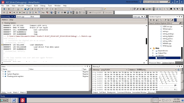
I can not overstate the importance of this feature. The ability to examine the assembly code, compare it to the source, and to step through it line-by-line is an enormous asset to the inline assembly programmer. You can, among other features:
• Set breakpoints
• Watch variables
• Alter register values
• Time sections of code.
You will want to remember how to do this.
ATMEL has uploaded several informative videos on youtube.com demonstrating the use of the Studio, how to debug and how to use the simulator. A good example is located here:
Also available as a book, with greatly expanded coverage!

[click on the image]
Here’s a partial look at the disassembly listing (mixed C and assembly) produced by AS7:
void setup() {
  // initialize the digital pin as an output.
  pinMode(led, OUTPUT);
0000007B  LDI R22,0x01		Load immediate
0000007C  LDS R24,0x0100		Load direct from data space
0000007E  JMP 0x000001A5		Jump
  pinMode(led, OUTPUT);
}

// the loop routine runs over and over again forever:
void loop() {
00000080  PUSH R28		Push register on stack
00000081  PUSH R29		Push register on stack
  digitalWrite(led, HIGH);   // turn the LED on (HIGH is the voltage level)
00000082  LDI R28,0x00		Load immediate
00000083  LDI R29,0x01		Load immediate
00000084  LDI R22,0x01		Load immediate
00000085  LDD R24,Y+0		Load indirect with displacement
00000086  CALL 0x000001E1		Call subroutine
  delay(5000);               // wait for a second
00000088  LDI R22,0x88		Load immediate
00000089  LDI R23,0x13		Load immediate
0000008A  LDI R24,0x00		Load immediate
0000008B  LDI R25,0x00		Load immediate
0000008C  CALL 0x00000119		Call subroutine
  digitalWrite(led, LOW);    // turn the LED off by making the voltage LOW
0000008E  LDI R22,0x00		Load immediate
0000008F  LDD R24,Y+0		Load indirect with displacement
00000090  CALL 0x000001E1		Call subroutine
  delay(1000);               // wait for a second
00000092  LDI R22,0xE8		Load immediate
00000093  LDI R23,0x03		Load immediate
00000094  LDI R24,0x00		Load immediate
00000095  LDI R25,0x00		Load immediate
}
00000096  POP R29		Pop register from stack
00000097  POP R28		Pop register from stack
  delay(1000);               // wait for a second
00000098  JMP 0x00000119		Jump
