

My GPS Predictive Lap Timer Project needs more memory than the typical Arduino contains. However, it occurred to me that I could use a Microchip 23K256 32KB SRAM SPI memory chip and not need to revert to an Arduino Mega or beyond. So I purchased a few 23K256 chips and began an investigation into SPI. Simple, right?
I read the 23K256 datasheet and searched the web to see what others did in an attempt to get the chips to interface with the Arduino. The first problem was the chips have a maximum operating voltage of 3.6V. Easy, I could power them with the 3V3 pin from the Arduino.
The second problem was writing the SPI interface software. Luckily there’s plenty of examples scattered across the internet, including a slightly dated library in the Arduino Playground (1 of 2 links fail). So as I usually do, I kludged together a simple test program.
Here is my program:
#include <SPI.h>

//SRAM opcodes
#define RDSR 5
#define WRSR 1
#define READ 3
#define WRITE 2

uint8_t SpiRAMRead8(uint16_t address) {
  uint8_t read_byte;

  PORTB &= ~(1<<PORTB2); //set SPI_SS low
  SPI.transfer(READ);
  SPI.transfer((char)(address >> 8));
  SPI.transfer((char)address);
  read_byte = SPI.transfer(0xFF);
  PORTB |= (1<<PORTB2); //set SPI_SS high
  return read_byte;
}

void SpiRAMWrite8(uint16_t address, uint8_t data_byte) {
  PORTB &= ~(1<<PORTB2); //set SPI_SS low
  SPI.transfer(WRITE);
  SPI.transfer((char)(address >> 8));
  SPI.transfer((char)address);
  SPI.transfer(data_byte);
  PORTB |= (1<<PORTB2); //set SPI_SS high
}

void setup(void) {
  uint16_t addr;
  uint8_t i;

  Serial.begin(9600);
  SPI.begin();
  for (addr=0; addr<32; addr++) {
    SpiRAMWrite8(addr, (uint8_t)addr);
    Serial.print("Addr: ");
    Serial.print(addr);
    i = SpiRAMRead8(addr);
    Serial.print(" | Read: ");
    Serial.println((uint16_t)i);
  }
}

void loop() {
}
The third problem is the chips use low logic level voltage. From the datasheet, minimum HIGH is 0.7*Vcc (2.31V) while maximum is Vcc+0.3 (3.6V). LOW side maximum is 0.2*Vcc (0.72V). The 5V powered Arduino levels probably wouldn’t work. I couldn’t simply wire directly between the Arduino and 23K256, it would probably damage the 23K256.
So I used a SparkFun Logic Level Converter between the Arduino SPI Clock pin (D13) and MOSI pin (D11). And actually, the Chip Select pin (D10) should run through level conversion too. The 23K256 data out pin (MISO) doesn’t require conversion.
However, I couldn’t get the chip to function. My test program was returning values, but they were gibberish. Something was clearly wrong.
I experimented over the course of several days with substituting an Adafruit TXB0108 Bidirectional Level Shifter. I searched the web and discovered many people had similar problems getting these chips to operate. I even tried using a few resister pair/voltage dividers in place of the level shifter. I began to get very skeptical of anyone that claimed they made these chips work. I searched the web some more and re-read the datasheet (there’s also a Microchip Application Note). I added a 10K ohm pull-up resister to the CS pin, but still gibberish.
Eventually I swallowed my pride and wrote a “help-wanted” post on the Arduino Forum. A few responses later I recieved a solution! I needed to tie the 23K256 HOLD pin high. While the datasheet doesn’t specifically state that, after countless re-readings I’ll admit it hints at it.
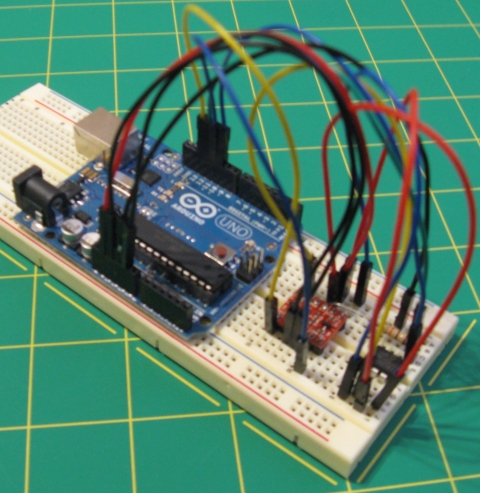
Here is the wire routing I finally used:
Arduino--Logic Conv--23K256
D13------TXH/TXL-----6.SCK
D12------------------2.MISO
D11------TXH/TXL-----5.MOSI
D10------------------1.CS
3V3------LV
5V-------HV
GND------HV GND
GND------------------4.VSS
3V3------------------8.VCC
3V3------------------7.HOLD
3V3------[10KR]------1.CS
Next experiment is to see if the speed of the 23K256 chip is fast enough to allow a 10Hz GPS update rate with my GPS Predictive Lap Timer Project…

How exactly does the following code work:
PORTB |= (1<<PORTB2);
So this I assume does the same thing as PORTB |= B00000100
But I don't know what PORTB2 is; is it a byte? If B2 is set high, does PORTB2 = B00000100?
Why are you left shifting by 1?
Thanks for any help
I’m speaking AVR.
Actually, I am setting a bit in the PORT.
PORTB2 specifies bit 2 in PORTB (PORTB2 is defined inside an included AVR header file). And since the bit number always starts at 0 and increases by 1 for each bit (8 bit numbers 0-7), we make a bit mask with the corresponding bit number. We build the mask by LEFT SHIFTING a bit (0x01 or 1) by the bit number (PORTB2 or 2). So, to build a bit mask that has bit number 2 set, we write:
Likewise, to build a bit mask for bit number 7, we would write:
And to build a bit mask that has bit number 0 set:
Which ends up shifting the constant 0 bytes to the left, leaving it at 1.
And we can easily make a mask with multiple bits like so:
And yes, it is doing the same thing as PORTB |= B00000100.
Hi, I found your article very interesting as I’m looking what the limits are for an Arduino.
What I also found was this one: http://hackaday.com/2011/09/07/want-2-megabytes-of-sram-for-your-arduino/
This is where they are able to assign up to 2MB to the Arduino using an Amani 64.
Maybe you already read that, else I hope it can be of help to you 😉
Greets Ruben
hi,
i want to use this microchip 23a256 or 23k256 serial sram with 8051 microcontroler
please give send me the c code to read and write the data from and to the 23k256 serial sram.
my email id is: xxx@gmail.com
advance thanks to you.
Basic code for the arduino posted here can be adapted.
Can you confirm if you directly connect pin D10 from Arduino to CS, as you described:
D10——————1.CS
Wouldn’t this damage the SRAM?
For testing the chip, I connected D10 directly to the CS pin. However, as I stated, “And actually, the Chip Select pin (D10) should run through level conversion too.”
If I run your code using the same setup and routing on the sparkfun chip, but leaving the CS connected to D10, will it work? Thanks in advance
It will work. However, I wouldn’t build anything more than a simple test rig without a level-shift on the CS pin.
Managed to get this chip working today with my Arduino Uno. Got the speed up to SPI_CLOCK_DIV2. I didn’t have any logic level shifters and initially was feeding resistor divider pairs into op amp voltage followers (I had a spare quad package lying around). Getting unexpected (tho’ predictable) results, almost like I was missing the odd clock cycle or two when shifting the data in/out. Decided to ditch the op amps and feed directly from resistor dividers using values of 100 & 330ohms. SUCCESS!!!
I too get angry with blindness strikes. The Microchip datasheet does a little more than hint wrt HOLD. Figure 1.1 HOLD timing clearly shows the influence of its function; if timing diargrams aren’t your thing then Section 2.1 Principles of operation states:
“The CS pin must be low and the HOLD pin must be high for the entire operation.”
I feel your frustration.
Come on now, who really reads the “Principles of Operation” section?
Thanks a lot, I tried something similar for a couple of days and and couldn’t get it working. You article helped to get the job done.
Instead of using Arduino + level shifters, I eased my pain and used the ATmega328P directly on bread board, with a VCC of 3.3V.
I was connecting it to the 5V pin and was not asserting HOLD HIGH. Thanks for your help!